Terrain Atlas of the Lunar Equatorial Belt
I — INTRODUCTION
A. Purpose and Scope:
The lunar equatorial belt between 60° W and 60° E longitude and 10° N to 10° S latitude was the area initially designated by N.A.S.A. for lunar exploration by unmanned space vehicles. The detail of lunar surface in this belt thus became a problem of immediate concern. Since terrain analysis is the study of landforms and their characteristics such as slope, type of surface, areal distribution of a given landform, this lunar study, because of the distance problem involved and the general character of the regional data, is designed to work from qualitatively-derived data through statistical analysis derived from photoclinometric slope-measuring to terrain units, each of which in their final derivation has a set of statistical values unique to that terrain wherever it occurs on the lunar surface. This atlas sets forth the results of this study and portrays the lunar terrain conditions as discerned from source data of 1 km resolution provided from earth-based telescopes either by photographic records or direct observations.
The Aeronautical Chart Information Service series of lunar charts (LAC charts) at 1:1,000,000 showing the lunar surface forms and relative relief, prepared by direct observation of the lunar surface, are the base maps used for plotting terrain data. The U.S. Geological Survey Special Map series on Lunar Geology, together with study of lunar photographs from the collections of various observatories and from direct lunar observation at the U.S. Geological Survey telescope in Flagstaff and other telescopes at Mt. Wilson and Kitt Peak National Observatories, provided the source material utilized in this two-phase study of the lunar surface.
Six maps, 20° x 20° in area, were designed to cover the equatorial belt, each map being a composite of 4, 10° x 10° sections of the 14 LAC charts which cover the belt. The names of the respective source charts appear on the margin of the individual terrain maps.
The evaluation of terrain units was accomplished by photoclinometric techniques which were combined with relative relief data derived by shadow measurements technique (Kopal, 1962) furnished by the Air Force Chart and Information Center, St. Louis, Missouri.
B. Method of Study
A preliminary group of terrain units was delineated on the basis of data presented on the 1:1,000,000 lunar geologic maps, study of lunar photography as well as direct observation of the lunar surface. These units, described below (Terrain Description), were then analyzed by photoclinometric methods* to determine their slope parameters. In addition to the statistical slope analysis, statistical analysis was made of the relative relief for those units on which relief data** was available. Since the accumulation of relief data is a continuing process, probably more data is available presently than when the study was made. Terrain units, originally delineated on a qualitative basis, were then revised in accordance with the slope characteristics and relief parameters established by quantitative studies.
* See U.S. Geological Survey Annual Report—
** Data provided by Air Force Chart and Information Center, St. Louis, Missouri.
(1) Photoclinometric Technique
The term "photoclinometry" has been proposed to describe the method of deriving topographic slope information from the brightness distribution of lunar images (photographic or electronic) by calibrated photometric techniques. The word is designed to distinguish between the techniques of photogrammetry, on the one hand, and the general subject of lunar photometry, on the other. It is a restrictive term, limited to that aspect of lunar photometry concerned directly with the extraction of slope component data from monoscopic pictures.
The technique depends on an accurate knowledge of the lunar photometric function, an expression for the reflectance properties of the lunar surface. The geometric conditions for earth-based photoclinometry are considerably less complex than the geometry encountered in viewing the lunar surface from spacecraft (Figures 1 and 2).
[FIGURE 1 — Geometry of the lunar photometric function. Diagram showing a
surface element with the LOCAL VERTICAL and LOCAL HORIZONTAL axes and rays
"TO SUN" and "TO SENSOR"; angles i, e, and g.
Caption: "Figure 1 — Geometry of the lunar photometric function where i =
angle of incidence; e = angle of emittance; and g = phase angle."]
[FIGURE 2 — Graph of INTENSITY vs. BRIGHTNESS LONGITUDE IN DEGREES (axis from
about -80° through 0° to +180°).
Caption: "Figure 2 — Empirical lunar photometric function (after Willingham,
1964)."]
(2) Sampling Technique
Terrain classification by statistical methods is critically dependent upon the degree of morphologic uniformity of the sample area at the effective slope length or size of the sample cell used. Morphologic uniformity is essential so that only one slope component population or type of terrain is sampled at a time. Prior to selective sampling, it was, therefore, necessary to study the best available earth-based photography, U.S. Geological Survey geologic maps, and the LAC charts. Most sample areas were sufficiently monomorphic to yield representative statistical data for one unit or type. Multimorphic sampling was, however, conducted in certain areas, and it has proved to be of some value in establishing values for relative roughness. The Shröter F sample areas (Samples 1, 2, 3, 4, 5, and 6) contain both upland and mare-type terrain (Figure 3), but three different roughness categories can be recognized (Table I). Sample areas 1 and 2, and 4 and 6, are very similar, whereas Sample 3 is obviously rougher than the other four areas. Detailed comparison, however, shows that area 2 is somewhat rougher than area 1, and area 5 is slightly rougher than areas 4 and 6.
[FIGURE 3 — Map of the Shröter F region showing the boundaries of the slope
component samples (numbered 1-6) and the morphologic types.
Caption: "Figure 3 — Shröter F sample areas 1, 2, 3, 4, 5, and 6, showing the
boundaries of the slope component samples and the morphologic types."]
- - - - - - - - - - - - - - - - - - - - - - - - - - - - - - - - - - - - - - - -
TABLE I — Statistical values for sample areas in the multimorphic Shröter F area
- - - - - - - - - - - - - - - - - - - - - - - - - - - - - - - - - - - - - - - -
(Location for all samples: Lat. 7.1-10.0°N, Lon. 8.0-2.8°W)
Sample Area Number X̄_AL Med_AL σ_AL Slope Rev. 10-90% X̄_Ab Med_Ab
— — — — — — — — —
Shröter F SA 1 603 0.19 0.10 1.35 0.27 2.54 0.87 0.57
Shröter F SA 2 188 -0.19 -0.08 1.56 0.25 3.97 1.17 0.84
Shröter F SA 6 390 -0.57 -0.48 2.31 0.32 5.66 1.83 1.51
Shröter F SA 4 430 -0.23 -0.06 2.42 0.35 5.68 1.84 1.46
Shröter F SA 5 218 -0.44 -0.56 2.63 0.32 6.52 2.03 1.66
Shröter F SA 3 270 0.51 0.73 3.63 0.38 9.33 2.87 2.32
Shröter F (Total)2300 -0.13 -0.06 2.34 0.33 5.29 1.67 1.18
- - - - - - - - - - - - - - - - - - - - - - - - - - - - - - - - - - - - - - - -
In general, the number of observations required to adequately sample a slope component population is dependent upon the roughness characteristics. About 100 observations generally suffice for the smooth, relatively homogeneous areas; 200-300 are required in the more complex areas. The sampling procedure is determined, therefore, by the terrain characteristics themselves, their spatial distribution, and the resolution of the plates used.
In order to derive effective relative roughness parameters from slope component measurements, the effectiveness of the standard statistical measures derived from both absolute and algebraic frequency distributions was examined. These included: the median, the mode, standard deviation, σ, the arithmetic mean, X̄, kurtosis, skewness, the 10-90 percentile dispersion values, the absolute arithmetic mean, X̄_Ab, and the algebraic standard deviation, σ_AL, along with the percentage of slope reversals and the relative relief for each sample area. The last three parameters have proved to be the most efficient from the terrain classification standpoint. Data is presented for each terrain unit used in the atlas in terms of these parameters (Table II).
- - - - - - - - - - - - - - - - - - - - - - - - - - - - - - - - - - - - - - - -
TABLE II — Limiting relative roughness values for major terrain units at one-kilometer resolution
- - - - - - - - - - - - - - - - - - - - - - - - - - - - - - - - - - - - - - - -
SLOPE COMPONENT RELATIVE RELIEF
X̄_Ab σ_AL % Slope Rev. x̄ σ Mode
— — — — — — —
Smooth Mare I-A 1.00° 1.27° 21.0% — — —
Rougher Mare I-A 1.00-1.78° 1.27-2.30° 21.0-26.5% 512 m 260 m 475 m
Uplands II-B 1.78-2.28° 2.27-2.90° 26.5-29.5% 626 m 281 m 375 m / 775 m
Uplands II-C 2.28° 2.90° 29.5% 757 m 402 m 525 m / 725 m
Uplands II-D (≥2.28°) (≥2.90°) (≥29.5%) 746 m 455 m 425 m / 1025 m
Crater Floors II-B-2 1.00-1.20° 1.50-1.83° 22.0-24.0% — — —
- - - - - - - - - - - - - - - - - - - - - - - - - - - - - - - - - - - - - - - -
(For Uplands II-C and II-D the slope-component cells "2.28°", "2.90°", "29.5%" are merged across both rows in the original. The Mode column shows two values for the upland units, reflecting bimodal relief distributions.)
[TABLE III — "Relative Roughness Scale for Some Terrain Units." This is a
GRAPH (scatter plot) of X̄_Ab (in degrees) versus σ_AL (in degrees), with a
diagonal trend line and zones labelled SMOOTH MARE, ROUGH MARE, CRATER FLOORS
AND RIMS, UPLAND SMOOTH, UPLAND HUMMOCKY, and UPLAND ROUGH.
Legend:
1 - Mare, I-A
2 - Rougher Mare, I-A
3 - Upland, Plains, II-A
4 - Upland, Hummocky, II-B
5 - Upland, Rough, II-C and II-D
6 - Craters, Floors, III
7 - Domes, IV-B]
[TABLE IV — "Relative relief frequency histograms." A column of frequency
histograms (RELATIVE RELIEF IN METERS on the horizontal axis).
Caption: "Table IV — Relative relief frequency histograms for: a, hummocky
upland, II-B; b, hummocky upland with moderate relief, II-C; c, sculptured
upland with moderate to high relief, II-D."]
An additional important consideration in any expression for relative roughness is the percentage of slope reversals per unit area. This is a measure of the frequency of the topography, whereas σ_AL can be thought of as a partial measure of its diversity. Slope reversal is related indirectly to the magnitude, i.e., amplitude, of the relief features; the terrain with the greater frequency of slope reversals would be a rougher terrain.
When the percent of slope reversal is plotted against σ_AL, a large amount of scatter results, suggesting that the two parameters may be essentially independent of one another. It may, therefore, be a fundamental classification parameter in the same sense that amplitude and frequency are necessary to the definition of a periodic function (Table III).
(4) Relative Relief Statistics
The final parameter used to evaluate terrain was relative relief. The relief data used were furnished by the Air Force Chart and Information Center, St. Louis, Missouri, and consist of approximately 1,200 measurements made by the shadow technique (Kopal, 1962). Since the photoclinometric technique is somewhat ineffective in the rough highlands because a large fraction of the terrain is in shadow at low sun angles, some other type of slope information, however limited, had to be used to classify these areas (Table IV).
Extensive use of relative relief data is limited by the small number of measurements available at this time and the difficulty in acquiring additional satisfactory measurements. Since the percentage of slope reversals or topographic frequency and relative relief may be inversely related, relative relief would be considered a dependent variable. Two statistical parameters, then, appear to be the most important from the general terrain standpoint—the algebraic standard deviation, σ_AL, and the percentage of slope reversals.
(5) Statistical Parameters
Table II gives the calculated standard statistical parameters for a number of terrain types where data were available, and the frequency distributions are shown in Table IV. These distributions are all bimodal, suggesting that the measurements were made on at least two distinct populations. The highland areas in the equatorial belt are indeed a composite of several types of terrain consisting of: (1) rugged hills and intervening valleys of structural origin;
(2) hummocky terrain related presumably to the Imbrium event; and (3) superimposed old and young craters.
Relative relief data clearly discriminate hummocky uplands, II-B, from the more rugged sculptured uplands, II-C and II-D. Effective detailed quantitative classification is, however, difficult, due to this heterogeneity. During terrain mapping of these areas, qualitative estimates of relative roughness had to be relied upon.
II — TERRAIN DESCRIPTION
A. General
The terrain of the lunar equatorial zone presents as wide a variety of terrain phenomena as any other zone of lunar surface although some of the type terrain areas lie outside the equatorial belt. Mare and uplands are the two fundamental morphologic types. To the west, mare and the phenomena indigenous to its surface, together with large impact craters such as Copernicus and Kepler, are dominant terrain. To the east, the upland and its phenomena dominate, and the character of the mare changes markedly, primarily because of the difference in total mare area compared to terrae mass.
The lunar surface can be subdivided into mare and uplands which are the two fundamental morphologic types. Superimposed on both mare and uplands are two other morphologic types, craters and linear features such as ridges, rilles, domes, ray systems and faults. These superimposed features create a wide variety of surface expressions and in themselves, particularly the craters, present such a variety in size and shape characteristics that they appear to dominate the fundamental terrain types whereas the linear features, though important from the standpoint of overall distribution of mare and uplands, are less commanding in appearance.
In general, the mare surface is considered lower in elevation than the uplands; the surface relief is relatively gentle and its surface reflectivity generally low (low albedo). Mare surface is considered smooth but wide troughs and plateaus, scarp bordered in some places, together with superimposed ridges, rilles, domes and craters give relief and character to the mare surface. The albedo of mare surface in places is outstandingly dark—and the term "dark mare" has been used to designate such areas because they may represent a young surface usually uncomplicated by many superimposed phenomena, particularly craters.
The upland surface, in contrast, is rugged and complex; superimposed linear features are more outstanding features on the uplands than in the less marked relief of the mare.
On the basis of careful analysis, a fourfold subdivision of the uplands has been discerned and designated areas II-A, II-B, II-C and II-D. The plains, II-A, frequently occur at the mare-upland boundary, but occurrence of plains in interior basins of structural origin or in floors of highly modified large craters is also common. These plains are morphologically similar in albedo to the mare but typically have higher albedo and crater densities. Upland hummocky terrain, II-B, is widely distributed around Mare Imbrium and is clearly dissimilar to the other subunits. The remaining upland types, II-C and II-D, are characterized by linearly arranged ridges and troughs. Local relief is moderate in areas designated II-C while it is marked in II-D terrain.
Among the superimposed or modifying features, craters include two main categories: well-formed with or without associated bright rays are designated III-A; craters modified and subdued in form, III-B. In each of these categories, morphologic subunits may be distinguished among the larger craters (10-50 km in diameter) (Figure ). Among those craters 10 to 20 km in diameter, component parts are indistinguishable at 1 km resolution; therefore, these are designated III-A or III-B only. However, smaller craters, less than 2 km in diameter, cannot be classified as to type, and are, therefore, designated III-C, undifferentiated craters.
Linear features constitute the second major group of modifying terrain units. Domes, ridges, rilles—both straight and sinuous, escarpments, chain craters, troughs and plateau areas, faults and lineaments each have individual and identifiable topographic expression. (See terrain unit types illustrations.) The frequency of any one of these types within an area may be such that they dominate the terrain pattern, markedly altering the surface roughness, or their presence may be a diagnostic characteristic of the unit, for example — Upland Units II-C and II-D.
The lunar terrain units based on the foregoing general types is outlined below. On the accompanying terrain maps, only those terrain units occurring on the map are described in the legend; therefore, the units listed below present the complete classification.
B. Definition of Terrain Units.
I - MARE
I-A Mare, Undifferentiated
I-B Mare, Dark
II - UPLANDS
II-A Upland, Plains Areas
II-B Upland, Hummocky to Subdued Topography
II-C Upland, Hummocky Topography with Moderate Local Relief
II-D Upland, Rough Topography with Large Variations of Local Relief and a High Incidence of Pronounced Linear Structures
III - CRATERS
III-A Well-formed Craters with or without Associated Bright Rays
III-A-1 Wall (interior): undifferentiated
III-A-1a Wall (interior): terraced or scalloped walls or detached blocks of wall material; well-developed talus
III-A-1b Wall (interior): moderately smooth
III-A-2 Floor: undifferentiated
III-A-2a Floor: smooth areas of generally limited extent
III-A-2b Floor: hummocky morphology
III-A-2c Peaks: generally located at or near the center of the floor
III-A-3 Rim: undifferentiated
III-A-3a Rim: hummocky topography, generally proximal to the rim crest
III-A-3b Rim: topography consisting of radial ridges and troughs, distal to hummocky area on rim
III-B Modified Craters, Generally of Subdued Form: Includes Large and Small Craters whose Rim and Inner Wall Slopes are Smoothed and not Readily Distinguishable
III-B-1 Wall (interior): undifferentiated, but generally smooth
III-B-2 Floor: undifferentiated
III-B-2a Floor: smooth areas generally within large, markedly deformed, craters on upland
III-B-2b Floor: rough, marked by slump blocks, hummocks
III-B-2c Peaks: centrally located; relative relief above crater floor is generally less than those of III-A-2c unit
III-B-3 Rim: subdued, hummocky topography; on small craters, this topography cannot be fully resolved
III-C Crater Fields and Craters: Two Kilometers or Less
IV - LINEAR FEATURES
IV-A Ridges, both Linear and Sinuous, Located within the Mare
IV-B Domes: Craters Indicated where Resolvable at Approximately One Kilometer; some Domes Appear Rough-Textured at the Limit of Telescopic Resolution
IV-C-1 Rills (Rima): linear in mare or upland; generally bounded by clearly-defined walls
IV-C-2 Rills (Rima): sinuous; generally in upland; commonly originate in crater and in places terminate in small bifurcating rills
IV-D Plateaus: Bounded by Escarpments; Usually within Mare
IV-E Escarpments (Rupes)
IV-F Depressions: Irregular or with Ill-defined Boundaries
IV-G Chain Craters
REFERENCES
Carr, D. D., and Van Lopik, J. R., 1962, Terrain quantification, phase I: surface geometry measurements: Dallas, Texas Instruments, Inc.
Carr, D. D., Becker, R. E., and Van Lopik, J. R., 1963, Terrain quantification, phase II: playa and miscellaneous studies: Dallas, Texas Instruments, Inc.
Diggelen, J. van, 1951, A photometric investigation of the slopes and heights of the ranges and hills in the maria of the moon: Astron. Inst. Netherlands Bull., v. 11, p. 283-289.
Fedoretz, V. A., 1952, Photographic photometry of lunar surface (in Russian): Kharkov Univ. Astron. Observ., Tr., v. 2, p. 49-172; also, Kharkov Univ. Uch. Zap., v. 42, p. 49-172.
Kopal, Zdenek, 1962, Topography of the moon, in Kopal, Zdenek (ed.), Physics and Astronomy of the Moon, New York, Academic Press, p. 251-282.
Kuiper, G. P., (editor), Photographic Lunar Atlas, Univ. of Chicago Press, 1960.
— (editor) Orthographic Atlas of the Moon, Supplement Number One to Photographic Lunar Atlas: Univ. of Arizona Press, 1961.
McCauley, J. F., 1964, Terrain analysis of the lunar equatorial belt: U.S. Geol. Survey open-file report, July 1, 44 p.
Rindfleisch, T., 1965, A photometric method for deriving lunar topographic information: Jet Propulsion Lab. Tech. Rept., no. 32-786, 16 p.
Rowan, L. C., and McCauley, J. F., Lunar Terrain Analysis, Lunar Orbiter—Image Analysis Studies Report, U.S. Geological Survey Progress Rept. to NASA, May, 1965 - Jan., 1966, p. 89-127.
Strahler, A. N., 1954, Statistical analysis in geomorphic research: Jour. Geol., v. 62, no. 1, p. 1-25.
— 1956, Quantitative slope analysis: Geol. Soc. Amer. Bull., v. 67, p. 571-596.
Watson, K., Photoclinometry from Spacecraft Images, Lunar Orbiter—Image Analysis Studies Report, U.S. Geological Survey Progress Rept. to NASA, May 1, 1965 to Jan. 31, 1966, p. 119.
Whitaker, et al., Rectified Lunar Atlas, Supplement Number Two to the Photographic Lunar Atlas: Univ. of Arizona Press, 1963.
Wilhelms, D. E. and Trask, N. J., 1965, Preliminary geologic map of the equatorial belt, 1:5,000,000, in Astrogeologic Studies, Ann. Progress Rept., July 1, 1964 to July 1, 1965, map supp.
Wood, W. F., and Snell, J. B., 1959, Predictive methods in topographic analysis: I. Relief, slope and dissection in inch-to-the-mile maps in the United States: Headquarters, Quartermaster Research and Engineering Command, U.S. Army, Tech. Rept., EP-112, p. 1-31.
================================================================================
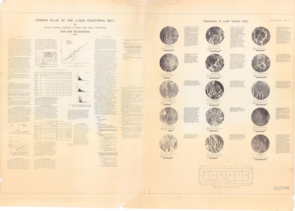
RIGHT PAGE — ILLUSTRATIONS OF LUNAR TERRAIN UNITS
================================================================================
[Each figure is a circular telescopic photograph. The caption (title, location,
plate, scale) and the descriptive paragraph that accompanies it are given
together below.]
- - - - - - - - - - - - - - - - - - - - - - - - - - - - - - - - - - - - - - - -
Fig. 1 — REINER CRATER AREA IN OCEANUS PROCELLARUM
Location: Lat. 8°N and Long. 53°W
Plate: ECD #75
Scale: 0 — 50 — 100 KM
Terrain units shown in this sector of the lunar surface are:
Unit IV-D - Plateau: Broad flat area rising above the general elevation of mare extends northward from Reiner Crater; margins in places appear sufficiently steep-sided to suggest escarpments; also, well-defined plateau to northeast surmounted by flatter elliptical domes.
Unit IV-B - Domes of Marius Hills Area: To the northwest of Unit IV-D are various elliptical hills, southernmost of the domes in the Marius Hills complex. Two dome types are shown: (a) low symmetrical to elliptical domes, commonly 3 to 15 km in diameter and up to 300 M in height, with small craters on crests or flanks; rarely, clefts appear along the crest with craters at one end; (b) asymmetrical, elliptical domes with side slopes ranging from 2° to 3° to 7°; domes having the latter slopes are typical and may have small pits near summit with fine "rille"-like structures.
Unit IV-A - Mare Ridges: sinuous ridges which vary from relatively simple curved type to intricately interlocking and bifurcating types.
Unit III-A-3a - Rim: Hummocky terrain occurs near the crest of rim; rough irregular hillocks.
Unit III-A-3b - Rim: Radial ridges and troughs distal to hummocky area on rim; merge outward into bands of ray material.
Both above units mask and subdue extensive areas of II-B topography and a few isolated areas of II-C. In this relationship between terrain features, the dominant type is labelled and the label for the subdued type appears in parenthesis under the dominant label.
- - - - - - - - - - - - - - - - - - - - - - - - - - - - - - - - - - - - - - - -
Fig. 2 — KEPLER CRATER
Location: Lat. 8.5°N and Long. 38°W
Plate: Pohn, U.S.G.S. 31" telescope, Flagstaff
Scale: 0 — 50 — 100 KM
Northeast quadrant shows the type area for II-B hummocky terrain. Several typical III-A craters with and without ray systems. In the southeast quadrant are two III-B type craters, one of which is flooded with mare; the southwestern quadrant is almost entirely mare (I-A) with a few mare ridges (IV-A) barely discernible.
- - - - - - - - - - - - - - - - - - - - - - - - - - - - - - - - - - - - - - - -
Fig. 3 — PROCELLARUM UPLANDS AND RIPHAEUS OF MARE PROCELLARUM
Location: Lat. 1.5°S, and Long. 20°W (Approx.)
Plate: Pease 124 C
Scale: 0 — 50 — 100 KM
This area shows relationships among several terrain types. In the southwest quadrant, dark mare I-B is associated with dome field (IV-B). In the southeast quadrant, marginal lowland (II-A) is present but is characterized by an albedo lower than other II-A types.
A well-defined linear feature - MARE RIDGE (IV-A) pattern extends from the northeast quadrant through the southwest quadrant.
- - - - - - - - - - - - - - - - - - - - - - - - - - - - - - - - - - - - - - - -
Fig. 4 — SINUS AESTUUM - INTERMARIA AREA
Location: Long. 15.5°W, and Lat. 7.5°N
Plate: Pease 124 C
Scale: 1:5,000,000 0 — 50 — 100 KM
Copernicus shows typically developed the features characterizing a III-A type crater: i.e., hummocky outer rim (III-A-3a), radial ridges and troughs (III-A-3b) merging outward with ray material; inner wall (III-A-1a) marked by slumping and faulting, a rough crater floor (III-A-2b) and crater peaks (III-A-2c), reported as high as the crater rim. A second III-A type crater appears to the northeast; this one preserves features of a Copernican crater but at present does not show the bright ray system merging with the radial ridges.
- - - - - - - - - - - - - - - - - - - - - - - - - - - - - - - - - - - - - - - -
Fig. 5 — AREA NORTHWEST OF PTOLEMAEUS CRATER
Location: Lat. 7°S and Long. 6°W
Plate: ECD #65
Scale: 0 — 50 — 100 KM
Unit II-C: Upland, hummocky topography with moderate local relief. Hummocky surfaces overlying older craters and other original relief; local relief characteristically marked. This area, south of Sinus Medii, is tilted northward.
- - - - - - - - - - - - - - - - - - - - - - - - - - - - - - - - - - - - - - - -
Fig. 6 — SOUTHERN SINUS MEDII AREA
Location: Lat. 0°N, and Long. 2°E (Mare Vaporum/Ptolemaeus Quadrangle)
Plate: ECD #63
Scale: 0 — 50 — 100 KM
A variety of terrain phenomena appear in this area:
Unit II-A: Upland, smooth area of the mare marginal type predominates, covering the south and east half of the terrain. It is light gray, low-lying, slightly cratered terrain which surrounds Sinus Medii; the latter feature is mostly mare (I-A).
In the northwest quadrant, two small Copernican craters illustrate rims (III-A-3) and smooth inner slopes (III-A-1b). Although floors are present in these craters, they are not visible in this photo.
DARK MARE (I-B) appears in the deep notch in the II-C upland; the latter is a hummocky area of moderate relief which occupies the southeast quadrant.
Several linear features are present: Two domes (IV-B), one with and one without summit crater, are directly south of point A. Rilles (IV-C-1), narrow but with well-defined border scarps, cross the southwest quadrant trending both east-west and northwest-southeast. A well-defined lineament along which craters are located trends across the II-C area—possibly a southerly extension of the Triesnecker Rima system. A III-B type crater is in the southwest quadrant.
- - - - - - - - - - - - - - - - - - - - - - - - - - - - - - - - - - - - - - - -
Fig. 7 — RILLE AREA BORDERING APPENNINE MOUNTAINS
Location: Lat. 25°N, and Long. 3°E (Approx.)
Plate: ECD #35
Scale: 0 — 50 — 100 KM
Terrain type IV-C: Sinuous rille approximately 80 km length lies within mare but marginal to the Appennine mountain area. Western end of rille heads in crater but a chain crater (IV-G) just north of crater at upland end of rille interrupts the continuity of the rille. Midway in the rille, a crater 9 km in diameter spreads debris across the rille. To the north, several smaller sinuous rilles in mare appear to head in craters on the uplands.
Appennine Mounts Area rises 3,000+ M (approx.) above the mare. In the southwest quadrant typical II-D type terrain with very rough surface and high relief, together with pronounced linear structures, is bordered on the north by a marked escarpment (IV-E). Also, three large areas of DARK MARE (I-B) occur in one of the dark mare's more common associations, i.e., adjacent to high marginal escarp-bordered uplands and a sinuous rille.
- - - - - - - - - - - - - - - - - - - - - - - - - - - - - - - - - - - - - - - -
Fig. 8 — AREA BETWEEN PTOLEMAEUS AND HIPPARCHUS CRATERS (Ptolemaeus Quad)
Location: Lat. 7.5°S and Long. 3°E
Plate: ECD #65
Scale: 0 — 50 — 100 KM
Terrain Unit II-D, Upland: rough topography with high relief and linear features. Area between Hipparchus and Ptolemaeus in the southern and southeast sectors shows II-D terrain marked by chain craters (IV-G) and lineaments. Regional tilt on this block is northward toward Sinus Medii; area slopes toward II-B terrain which in turn borders an extensive area of II-A lying around Sinus Medii.
- - - - - - - - - - - - - - - - - - - - - - - - - - - - - - - - - - - - - - - -
Fig. 9 — THEOPHILUS QUADRANGLE
Location: Lat. 11.5°S and Long. 10°E (Approx.)
Plate: ECD #86
Scale: 0 — 50 — 100 KM
II-A Upland: smooth plains area. Centered on Andel Crater. Plains visible in this area are on upland; particularly large plain on southwest. Only a few well-defined small craters (at 1 km resolution) are visible on these areas.
- - - - - - - - - - - - - - - - - - - - - - - - - - - - - - - - - - - - - - - -
Fig. 10 — KANT AREA (THEOPHILUS QUADRANGLE)
Location: Lat. 10°S and Long. 19°E (Approx.)
Plate: ECD #86
II-D Upland: rough topography in northeast with large variations of local relief and a high incidence of pronounced linear structures. Tilted block area within the terrae, inclined slightly to northeast toward Mare Tranquillitatis. Linear structures commonly chain craters (IV-G). Southwest margin of block plain visible.
- - - - - - - - - - - - - - - - - - - - - - - - - - - - - - - - - - - - - - - -
Fig. 11 — ALBATEGNIUS AREA
Location: Lat. 12°S, and Long. 4°E
Plate: ECD #18
Scale: 0 — 50 — 100 KM
Albategnius is a III-B type crater. Both rim (III-B-3) and inner slope (III-B-1) are subdued and those features which characterize the III-A type rim in particular, are not determinable.
Lower inner rim (III-B-1) retains determinable slump blocks, but slope is less steep. Outer rim has lost all determinable characteristics except slope; craters of this type in general are scored by lineaments and linear features such as chain craters (IV-G) and are markedly pitted by smaller craters, most commonly III-A types.
The crater floor is comparatively smooth (III-B-2a) though Ranger IX photos on the Alphonsus (similar type crater) floor reveal considerable relief, and a variety of crater types and sizes which are well below the 1 km resolution of ECD #18.
The central peaks (III-B-2c) are much lower than the surrounding rim in contrast to central peaks in the III-A type craters which may equal the rim in elevation.
- - - - - - - - - - - - - - - - - - - - - - - - - - - - - - - - - - - - - - - -
Fig. 12 — CRATER ARISTILLUS IN MARE IMBRIUM
Location: Lat. 35°N, and Long. 0°E
Plate: ECD #35
Scale: 0 — 50 — 100 KM
TYPICAL III-A TYPE CRATER with ray system: The rim area (III-A-3) shows the hummocky topography (III-A-3a) characteristic of these craters and, in addition, radial ridge topography (III-A-3b) which merges outward with rays, a condition characteristic of III-A crater outer rims.
Inner slope (III-A-1a) is terraced, with slump blocks; the floor area is smooth (III-A-2a) with a low, but well-defined group of central peaks (III-A-2c).
- - - - - - - - - - - - - - - - - - - - - - - - - - - - - - - - - - - - - - - -
Fig. 13 — RILLE SOUTHEAST OF SABINE CRATER
Location: Lat. 0°N and Long. 21°E
Plate: Ranger VIII, fb 441
Scale: 0 — 50 KM
Terrain unit IV-C-1: Rille (rima) straight. Two rilles interrupt the mare surface but to the northwest the rilles are masked by rubbly material which forms the southeast sector of the outer rim of Sabine Crater. The southernmost rille distinctly shows (a) border escarpments (IV-E), (b) a very flat rille floor, and (c) offsets in the escarpment rim. Chain craters (IV-G) lie across and small craters transect the rille escarpments.
- - - - - - - - - - - - - - - - - - - - - - - - - - - - - - - - - - - - - - - -
Fig. 14 — MARE SERENITATIS - EASTERN AREA
Location: Lat. 24.5°N, and Long. 26.5°E
Plate: ECD #29
Scale: 0 — 50 — 100 KM
Area lies southeast of Posidonius Crater. Broad MARE RIDGES (IV-A) show an echelon appearance created by overlap of numerous short ridges. This particular terrain feature is confined entirely to mare or marginal mare areas. Craters located on mare ridges may be indigenous to the ridge or may have been formed later.
On left of easternmost ridge, a lower dark mare (I-B) area appears which shows markedly the very dark albedo and the characteristically low density (2x - 3x lower where measured) of small craters compared to their density on normal mare (I-A) to left of ridges.
- - - - - - - - - - - - - - - - - - - - - - - - - - - - - - - - - - - - - - - -
Fig. 15 — CAUCHY RILLE AREA, MARE TRANQUILLITATIS, EAST HALF
Location: Lat. 10°N and Long. 38°E (Approx.)
Plate: Pic du Midi; 120″
Scale: 0 — 50 — 100 KM
Terrain Units shown in this sector are:
IV-B Mare Domes: Two elliptically-shaped domes near the southern margin of photo; southernmost has summit crater with small rille extending downslope to northeast. Relief is low in proportion to width. To west-northwest, a second dome has similar size and shape, but relief is higher and slopes steeper; may have summit spine.
IV-C-1 Rilles (Rima) linear in mare: bounded by clearly-defined walls. The northernmost Cauchy rille shows a relatively straight to gently curved narrow trench bounded by steep to precipitous walls; in some places these escarpments are faults; southernmost rim indicated by shadow.
IV-E Escarpment (Rupes): Southernmost Cauchy Rille shows clearly the precipitous northern rim, with a step-like slope or a long chain crater parallel to the middle sector. Although this southernmost feature has been named a rille, its appearance on many lunar photographs does not bear out the presence of a southern rim; therefore, it is designated here as an escarpment, possibly a fault.
- - - - - - - - - - - - - - - - - - - - - - - - - - - - - - - - - - - - - - - -
[INDEX MAP — "INDEX TO LOCATION OF LUNAR TERRAIN UNIT TYPE AREAS." A graticule
of the lunar equatorial belt (about 70°W to 60°E longitude, 20°N to 20°S
latitude) with the numbered figure locations (1-15) plotted, divided into
sectors I-VI.]
This report is preliminary and has not been edited or reviewed for conformity with U.S. Geological Survey standards and nomenclature.
================================================================================
END — Lunar Terrain Atlas, Sheet 7 of 7
================================================================================